As can be seen on the schematic, the circuit is just a minimal Atmega328 circuit, featuring the bare essentials required for operation as a decently comfortable cw-keyer:
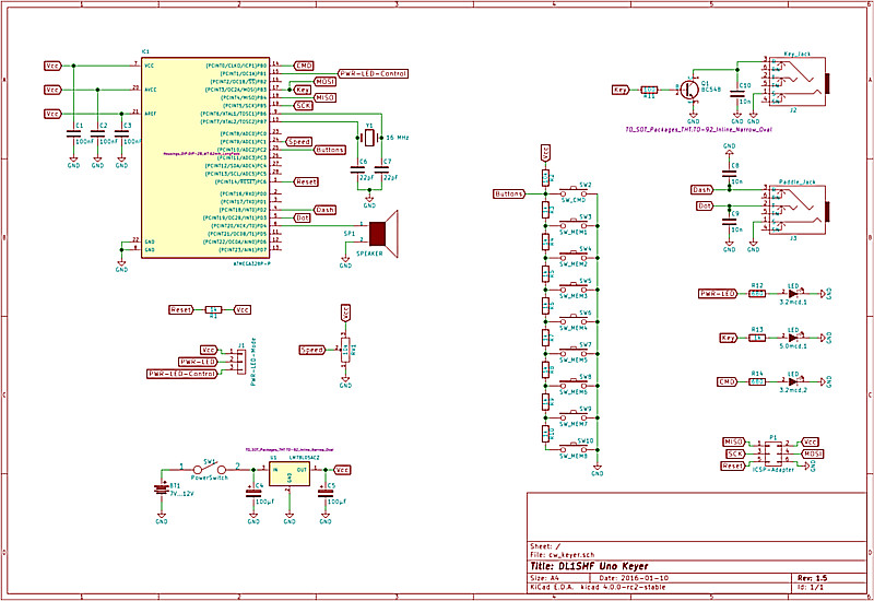
The above diagram shows Revision 1.5 of the schematic. You can download the most recent version either by clicking on the image or downloading the file cw_keyer.pdf from below. The circuit itself is pretty much self-explaining. The only things worth mentioning are that you of course can use regular LEDs but in that case need to adopt the resistors R12, R13 and R14 to (most probably) something around 330 to 470 Ohm. In case you do this, expect the battery to be drained a little bit quicker, so I cleary do not recommend it.
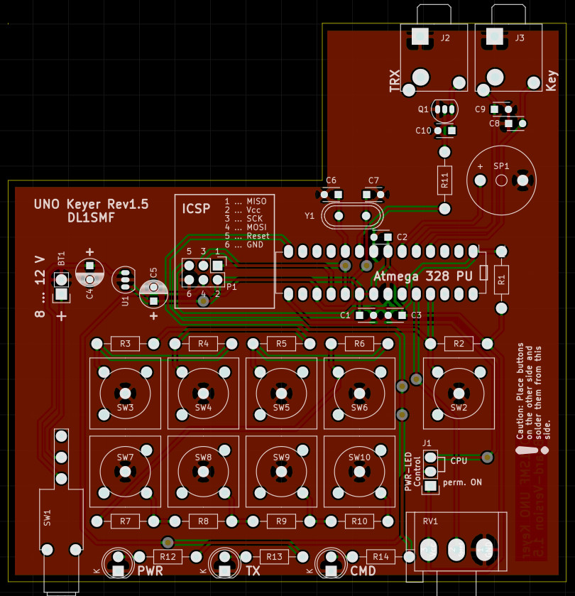
Either click on the above image or on the link (PCB.zip) below, to download the most recent version of the board. This file contains the KiCad 4.x.x PCB as well as Gerber-files. For manufacturing of the board: You will need vias and the design relies on the assumption that the board is plated-through. So, if you want to etch it by yourself, take care of this. If you are located somewhere in Europe I really can recommend obtaining a professionally manufactured board for the keyer from Jakob Kleinen (www.platinensammler.de). This is where I get my prototypes from and it's professional quality for an affordable price (approximately €35 for one board). It takes some time but it's really worth waiting for. If you're from anywhere else, you most probably should see if PCB-Pool (www.pcb-pool.com/) will deliver to your region.